A safe and reliable electrical installation is one that minimizes the probability of accidents that endanger the life and health of users, also reducing the possibility of failures in the electrical equipment available, avoiding the consequent investment of money necessary for its repair or replacement.
The reliability of an electrical installation is provided by three parameters:
– A good design.
– The use of qualified and certified labor at the time of installation.
– The use of suitable materials of guaranteed quality (that comply with the technical standards and regulations in force) in the installation.
Over time, the typical problems that can occur in an electrical installation are the increase in the electrical load of our installation and the deterioration of the elements that make it up, causing installation failures that can be translated, among others, in electrical accidents.
Another fact that guarantees the safety of our electrical installation is the validity of the materials that we are using in it. In this regard, we must bear in mind that the useful life of the electrical cables -which are responsible for transporting the energy in the installation- is 20 years, as long as: a) it is a good quality product, b) it has been correctly dimensioned for the number of appliances to be supplied with energy c) has not been overloaded during use.
Failure to comply with any of these situations significantly reduces the duration, for this reason it is recommended that the design of any installation that is close to turning 20 years from its commissioning be reviewed, redoing the corresponding analysis and changing the elements that make it up.
RUN, METER, BOARD
The energy that we receive in our facility can arrive in the air or underground. In either of these two ways, the Rush is the point through which electrical energy enters our Meter.
The Meter serves to count the electrical energy that is being consumed within the installation. Continuing on its way, the electrical energy reaches the general panel inside the installation.
We must remember that the general panel serves to properly manage the energy inside the user’s premises and, in addition, it is the place where the protection systems that provide safety to the user must be concentrated.
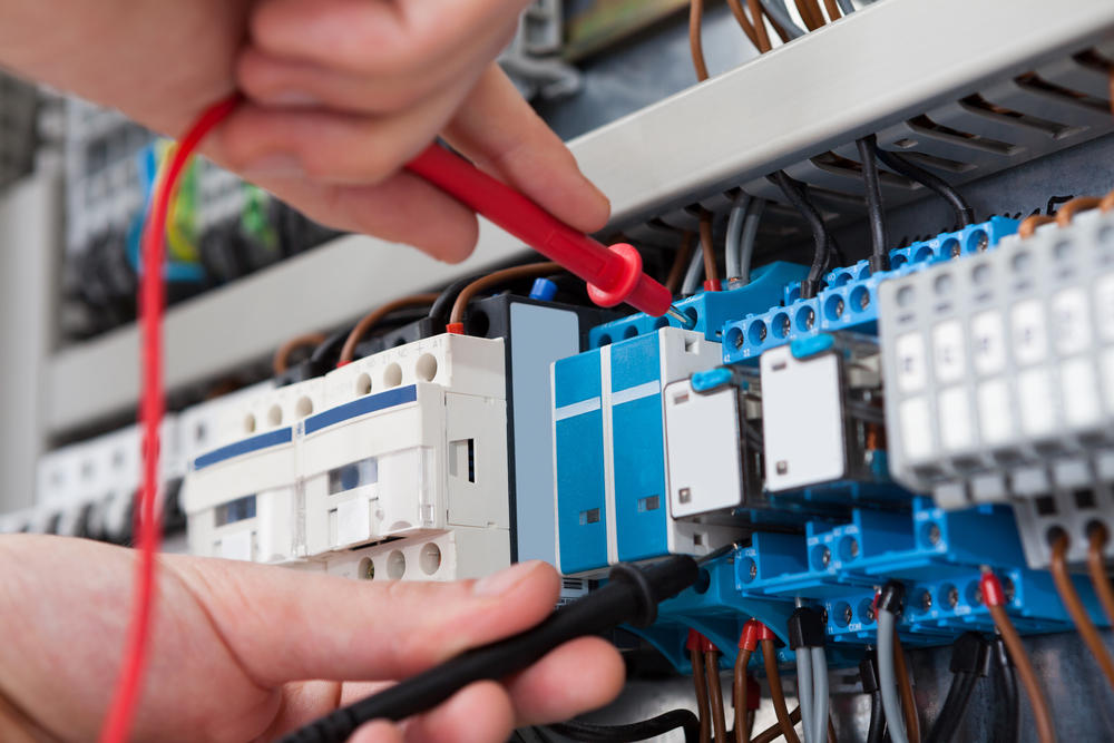
PROTECTION SYSTEMS
The protection switches will allow that, in the event of an electrical risk to the installation, the electrical power supply is automatically cut off.
These can be diverse. In old installations a blade wrench was used, with lead conductors as protection fuses that “opened” the circuit when a lot of current circulated through it, but since it does not provide the necessary safety, thermomagnetic switches are recommended to protect all electrical installation. Additionally, the use of differential switches is essential to protect people against the risks of electrocution.
Thermomagnetic switches act in the event of an overcurrent since, as there is an excess of electric current circulating, which translates into an increase in the temperature of said conductors (cables), they “open” the circuit avoiding greater damage such as the fires.
For their part, the differential switches act by “opening” when a “leakage current to earth” occurs in some part of the internal circuit, this discharge of electrical current to earth can occur through a person, generating a risk of death by electrocution.
ELECTRICAL SYSTEM CIRCUITS
It is recommended that three circuits come out of the general panel of any electrical installation: luminaire circuit, socket circuit and strong load circuit.
The first is aimed at all the luminaires in the installation (spotlights, fluorescent tubes, dichroic tubes, reflectors, etc.). The second should reach all the places where it is necessary to connect an electrical appliance. And the third must supply all the loads that consume high values of electric current (electric stove, electric heater, etc.)
This division of circuits is carried out in order to balance the total load of the electrical installation. According to the National Electricity Code, the minimum gauge of the conductors must be 2.5 mm².
THE GROUNDING OF THE ELECTRICAL SYSTEM
Likewise, the general board reaches the ground connection of the electrical installation and from there it must be distributed to 100% of the circuits: Lighting, outlets and strong loads. For this reason, the board shows a copper cable, usually bare, coming from the ground; and the ground wire, usually with green or yellow plastic insulation, that goes to the installation circuits. The National Electricity Code requires that 100% of the installation must be connected to the Ground.
THE DRIVERS
The electrical cables that come out of the board and go to the outlets, lights and strong loads must be correctly dimensioned in order to resist, not only the current electrical load but also the future electrical load that is going to be put in said installation., throughout its useful life.
Likewise, it is important to take into account the useful life of the conductors that we use is 20 years due to the natural aging of the insulating plastic, so in facilities with an operating time greater than this, the load analysis must be done corresponding and change the elements that make it up.
In many electrical installations, in order to “save money”, “alternative” electrical cables (substandard or false) are installed made of materials other than copper, with a smaller diameter or gauge than what should be used according to the amount of equipment used. will be connected to this cable, this causes an overheating of the cable, which translates into loss of energy that is paid in monthly consumption and a premature deterioration of its insulation, which finally ends up putting the bare copper conductors in contact and causing short circuits.
It is important that we become aware that every electrical wire or cable has a certain diameter due to which the amount of electrical current it can carry has a limit. The correct sizing of the electrical conductors of the interior electrical installation (the correct selection of the diameter / thickness of the cable to be used) will precisely ensure that in the future these conductors do not suffer from overheating, thus avoiding the presence of short circuits.
CIRCUIT OF CURRENT AND HEAVY LOAD
The outlet circuit that ends in each outlet of the installation must include the wire and ground, that is to say that each outlet must have three entrances.
According to the National Electricity Code, a maximum of 8 double outlets can be installed for each annular circuit. An annular circuit is the one that is formed by all the sockets that depend on a pair of power supply electrical conductors and a protection conductor, in conclusion, in each pair of electrical conductors only 8 double sockets should be installed at most.
On the devices to be used in the outlet circuits, there are safety regulations that allow them to function properly. It is very important to know the maximum current capacity of an outlet so as not to overload it with multiple splices and connections. It should also not be allowed to use the socket without a plug, that is, inserting the conductor directly into the socket, as this causes constant dangers in the connection and the possibility of a short circuit.
LUMINAIRES CIRCUIT
It is advisable to use energy saving equipment in the luminaire circuit, this equipment will reduce the users’ payment for electricity and enjoy a quality installation.
For luminaire circuits, switches that can adequately withstand the maximum current required by each connected load must be considered. Likewise, it is important to take into account that these switches comply with the Electrical Safety Standards that allow them a prolonged operation in number of operations, good insulation and good quality in their contacts.
SPACES AND JOINTS
In every connection and union that is made in an electrical installation, the quality of the electrical installation must be ensured. Splices and joints must be made ensuring a perfect union between the cables. To achieve this, it is important to take into account the quality of the elements used in this operation, including the protective tapes used on the joint.
The connections and splices must be used for the connection of the cables with the protection equipment of the general panel and for the derivations of the conductors in the connection to the outlets or lights.
On the other hand, connections and splices should not be used in order to join sections of cables of small lengths and in this way achieve sections of cables of greater lengths, because in this way possible points of false contact between conductors are introduced, which cause overheating, deterioration of insulation and possible short circuits.